Overview
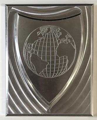
This project involved machining a precision aluminum plaque from engineering drawings, applying geometric dimensioning and tolerancing (GD&T) principles. The plaque serves as a practical exercise in translating design specifications into machined parts.
The work demonstrates the complete CAD/CAM/CNC workflow from design interpretation to finished part.
Technical Implementation
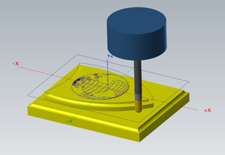
- CAM Programming: Created tool paths in MasterCAM for flat, ball-nose, and finishing endmills
- GD&T Application: Translated engineering drawings with precise dimensional and geometric tolerances
- Machining Strategy: Compared climb vs. conventional milling techniques for optimal surface finish
- Feedrate Optimization: Used MachPro software to analyze and optimize cutting parameters
- Quality Control: Verified dimensional accuracy and surface finish against specifications
Key Challenges & Solutions
- Tolerance Interpretation: Properly applying GD&T symbols to ensure functional requirements are met
- Tool Path Optimization: Selecting appropriate tools and strategies for different features
- Surface Finish: Achieving required surface roughness through milling parameter optimization
- Precision Machining: Maintaining tight tolerances across the entire part
Results & Impact
The plaque was successfully machined to specification, demonstrating proficiency in CNC programming and manufacturing processes. The project built practical intuition for CAD/CAM workflows and machining best practices.
This work provided hands-on experience with industrial manufacturing techniques and quality control.